This is a blog describing the process of setting up my LED Array project. It was my first time laying out a multi-layer PCB, so much of the process was about learning to work with KiCAD.
A lot of the inspiration for this project came from Phil's Lab STM32 help. I learned a lot of the basics of laying out components in a schematic and routing the schematic. I also am very thankful to my friend Miguel, who provided an extraordinary amount of guidance and advice.
Update (December 12 2025)
I once again have not really updated this site. I was hoping to be a lot more deliberate with updating, but some personal stuff came up and my semester kind of got ruined. I ended up getting a lot of work done for my UROP, but my overall life-balance was just really cooked.
Below is a (potentially boring) description of the logic. The software was also written in STM32IDE and can be found on my github. I was flashing the board with an ST-Link to test my board logic, but in the future I want to work on a bootloader for this.
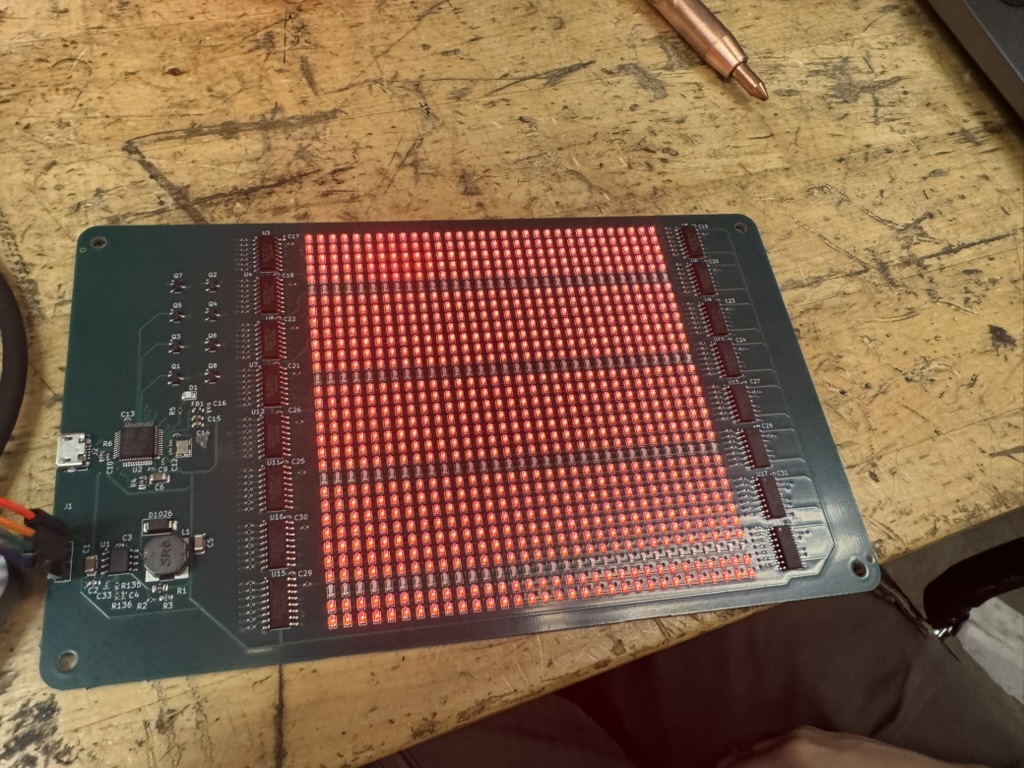
I have a current animations set up right now. I have dots that flash around the perimeter, a filling spiral, hearts that rise up, fireworks, an ILY message, and a heart with initials. Thankfully this project is winding down and I'm almost ready to give the gift to my girlfriend. That being said, I wanted to point out a couple things that I would change if I could do this in the future.
- Static Mode: Currently, the board is set up to be continually running. It would be nice if it was possible to change this from a state frame, like a heart, to the animated loop.
- Space Efficiency: I was not very efficient while setting up the board in terms of minimizing the space used. This was partially a reaction to me being pretty being and wanting to order the boards, however, I think I would have benefitted from taking the step and cutting down on empty space.
- Header Pins: It would be nice to not have the header pins on the PCB. I don't really like how they can be easily messed up. I think in an ideal world, I would have something to do to get them off. If/when I make a bootloader, I would like to desolder the header pins and take them off the board.
Update (November 15 2025)
I have not updated my website pretty much at all this past month. I've once again gotten hosed by my classes. This weekend though, I have some amount of spare time that is getting devoted to finishing up the LED Board project. I ordered it around October 31s and it was delivered to me on November 7th. A lot of time last week was devoted to my UROP, since I need to get the Ping360 on the boat this upcoming week. Also my classes are piling up and I'm realizing I'm not really getting more time this semester. I want to finish this up so I can focus on my MITERS project with Daniel.
Anyways, now I'm working my way through STM32IDE and trying to set up the firmware so I can flash the STM32 microcontroller. After getting some help finding an ST-Link to flash the STM32, I determined that it did work. I first had a blink code set up. I first had it powered off of the ST-Link, to confirm the STM32 was properly routed (not a huge concern, but somewhat big for my first time designing a PCB). After that, I looked at the voltage ripple on an oscilloscope, which showed a ripple of around 20 mV. I apparently didn't load the image on my thumb drive how i thought I had, so this will be uploaded later (we'll see about this lowkey, will maybe happen next time I'm MITERS).
Update (October 19 2025)
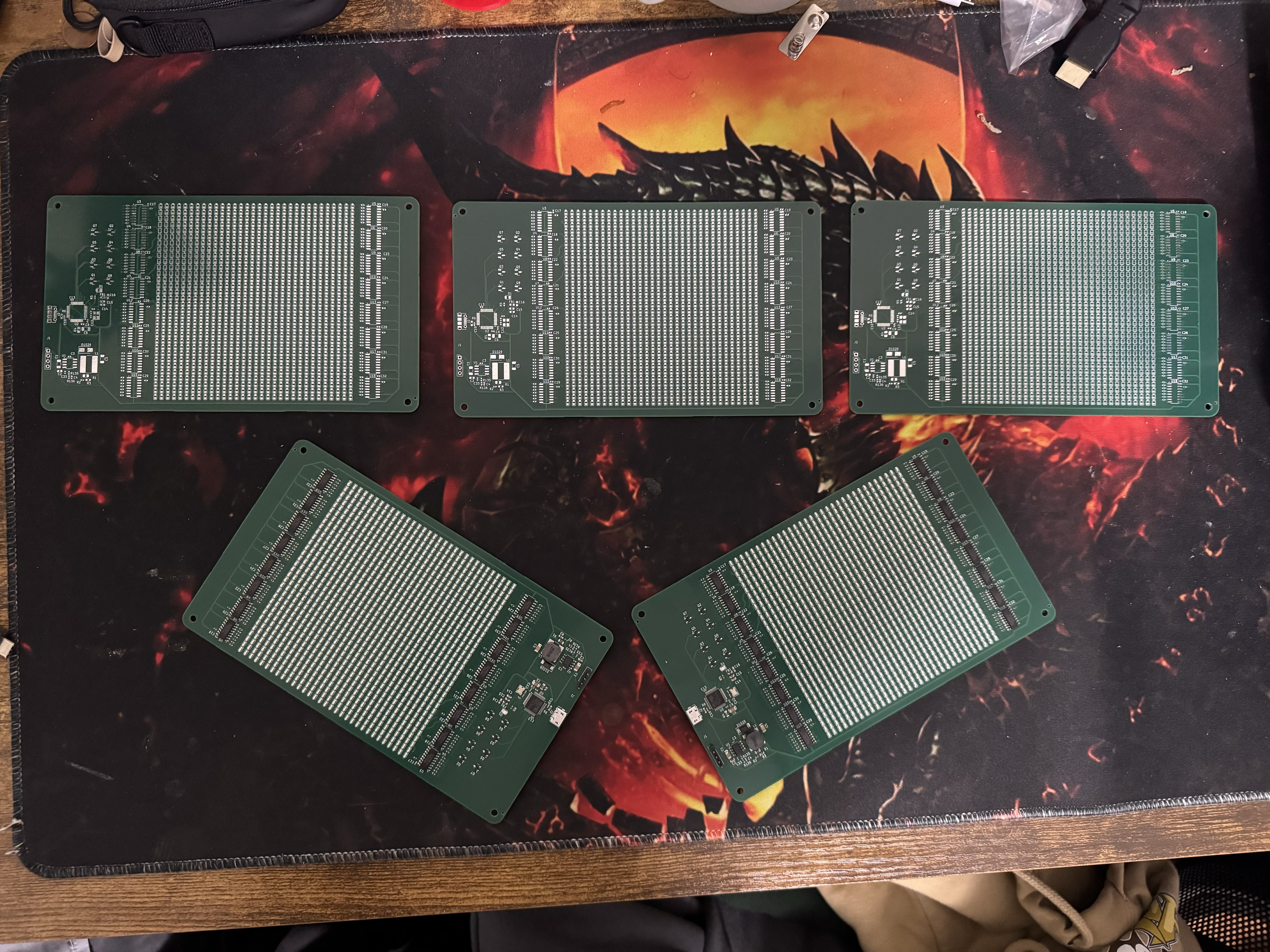
Yesterday I thought I was done, but I was getting some errors with LCSC fields and compatibility when I uploaded it to JLCPCB. I spent a few hours earlier working more on the LED Array and it's currently in JLCPCB ready to order. I'm doing a final look-over before I order it. Honestly, I'm really excited to order the PCB, but a little worried that it won't come out as well as I want it to. I'll update this hopefully later tonight with order information. I had to pivot one of the footprints so that it would work better with JLCPCB, but it's making my 3D viewer look a little wonky.
I am ordering the PCB and it looks to be \$81.18 for the product (5 PCBs, 2 Assembled), then \$39.43 for shipping and \$44.65 for custom duties and taxes. The grand total is almost \$170. This is kind of insane for a not crazy board. I'm going to look more carefully at this cost before I order actually. I don't think it needs to be this much. I'm going to ask the MITERS discord for thoughts before I buy.
Okay, it looks like I'll be able to get it down to \$154.21 with coupons. This is lowkey still a lot though, so I'm going to wait until a different day to order. I would really prefer not to spend another \$150 if I did something wrong, so I want to verify everything if possible.
Update (October 18 2025)
I am working on the Buck Converter right now. While looking through the data sheet for the TPS54331DR, I realized that there is a link to TI's Power Converter. It basically makes a potential schematic for the use case that you want. As such, I put an output ~ 2 A (overestimate for what we need), with an input voltage of 4.4 to 5.4 V that would output 3.3V.
They recommended a voltage divider into VSENSE with Rfbt = 10.2 kOhm and Rfbb = 3.24 kOhm. This is honestly a little ridiculous, so I'm finding a better combination.
V_sense needs to = .8V. I need V+out = V_ref * (1 + (R_top) / R_bottom). This means that I need R_top / R_bottom to equal 3.125.
They recommend resistor values that actually are higher than this, with 10.2 kOhms and 3.24 kOhm which is a ratio of 3.148. This might be something I should consider more.
I'm going to ignore this, stick with the .8V. I'm going to stick with trying to get 3.125. I'll have a 10 kOhm resistor on top and then two resistors (2 kOHm and 1.2 kOhm) in series to get an equivalent resistance equal to 3.2 kOhm. This will give me the desired ratio of 3.125.
Okay, I've gotten all the new parts laid out and everything. I think it's pretty ready right now. I'm going to have a friend with PCB design experience look over it.
Update (October 12 2025)
So it was not that easy. It was up to standards for ERC and DRC. I have realized though, that some of my initial decisions were just off. I want to verify my design before I spend money on it, so I'm going back, making sure my buck regulator is correctly set up (I'm almost now sure it is not) and making sure that I'm getting all of the basics. I will be doing some basic calculations as well just to be sure it's working when it arrives here. I'm setting a tentative buy date by Halloween.
Update (October 3 2025)
Now, I have been laying out the PCB for it. As of the time of writing right now (October 1st), it's pretty close to being done. I need to make sure it's all up to standards for ERC/DRC one last time and then I'll send it off to JLCPCB.
Update (September 6 2025)
I'm working on setting up the PCB-layout in KiCAD, which I have never done. There are 32x32 LEDs, so there's a lot of components to lay out and I don't want to do it on my own. Thankfully i have hierarchical sheets set up and am not trying to use replicate layout.
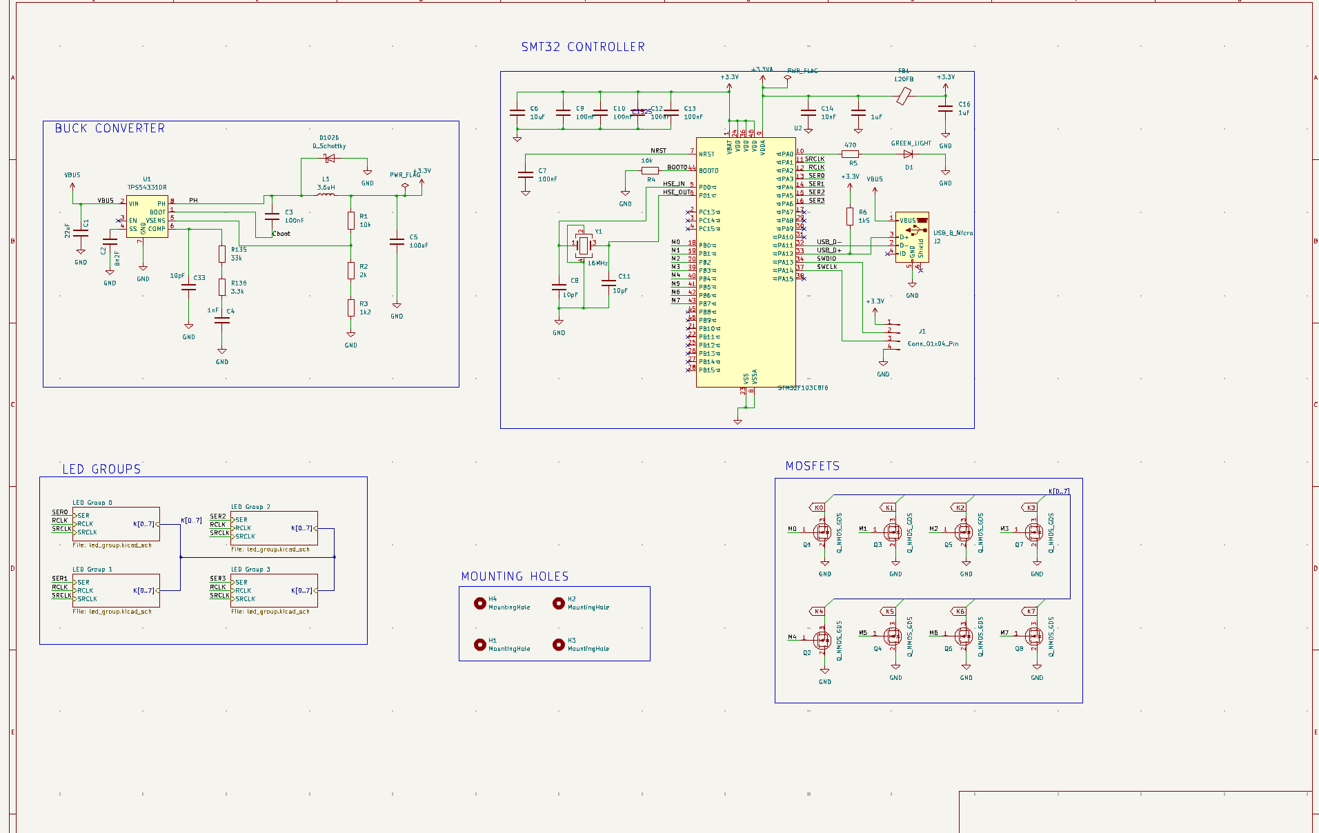
The schematic process was closely following what followed in the video. However, I decided to use a buck converter instead of the linear regulator for better efficiency and to try doing something new.
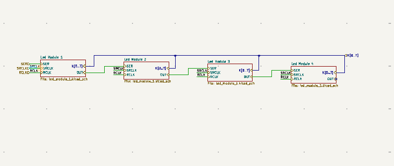
I decided to use hierarchical schematics for the LEDs to simplify the schematic and PCB process. I intended to use Replicate Layout, which can be downloaded in KiCAD's 'additional plug-ins manager.'
I was initially struggling to use it, but after a while of playing around with hierarchical sheets, I got the hang of it. Below are the current schematics that I'm hoping stick around.
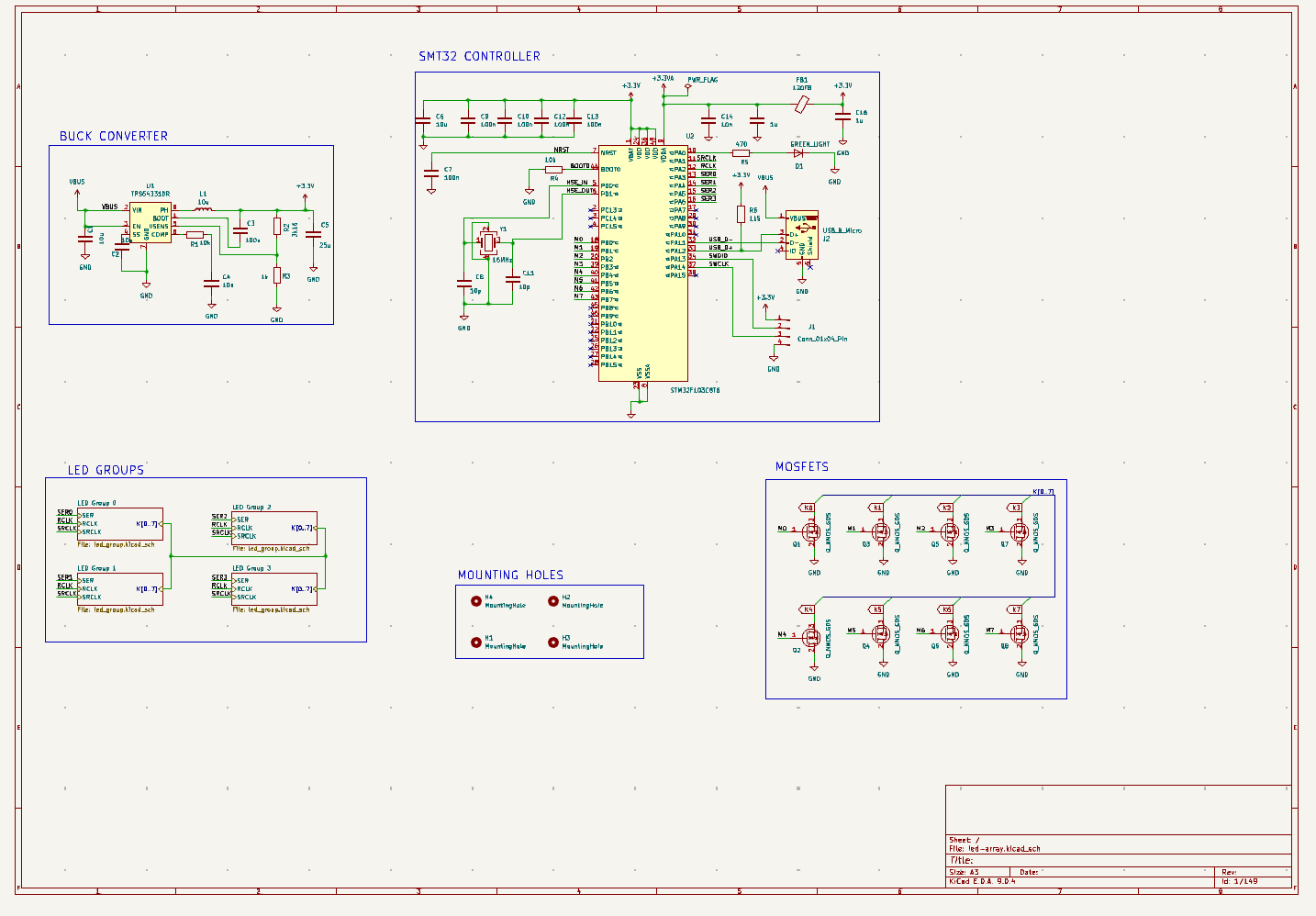
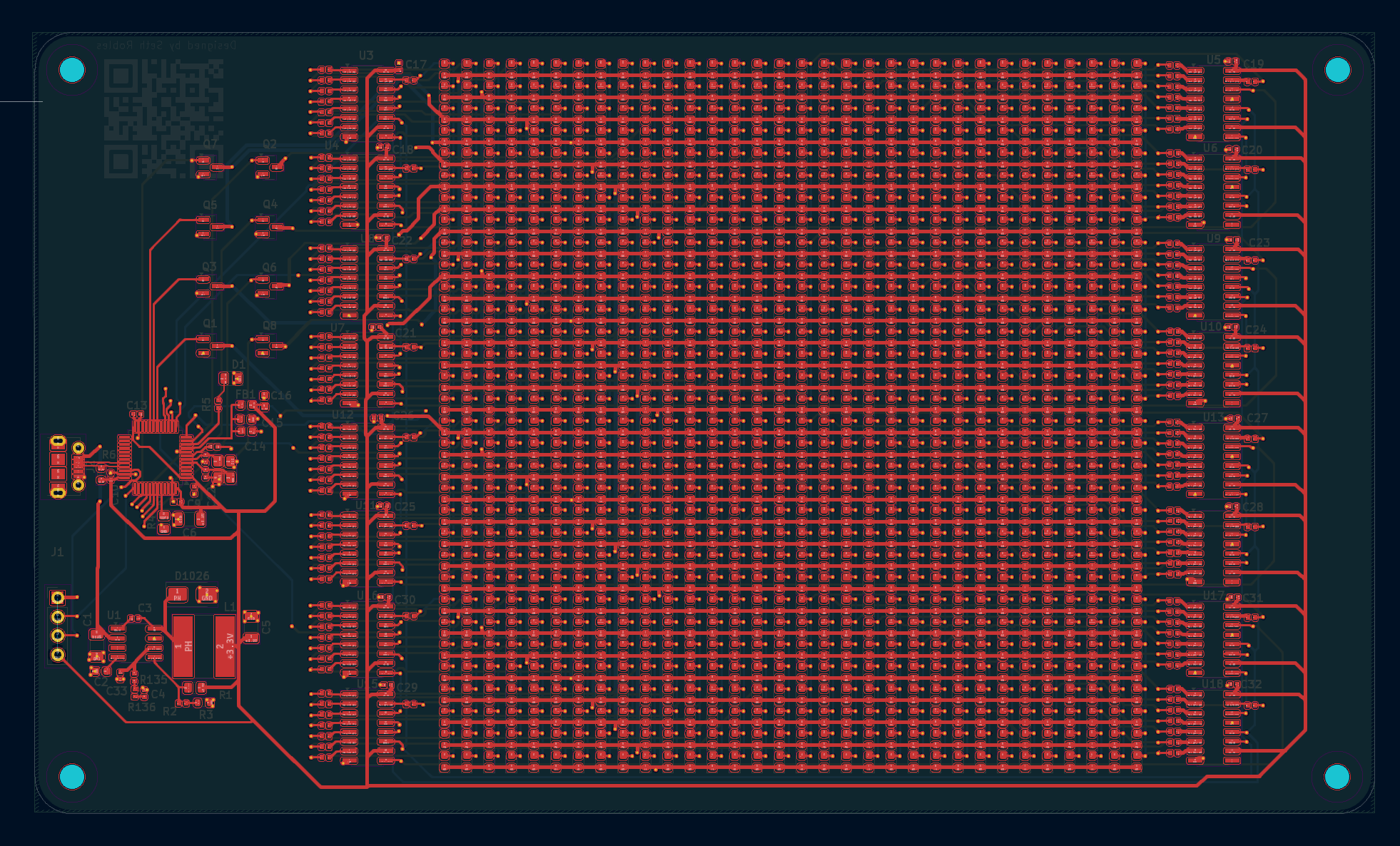
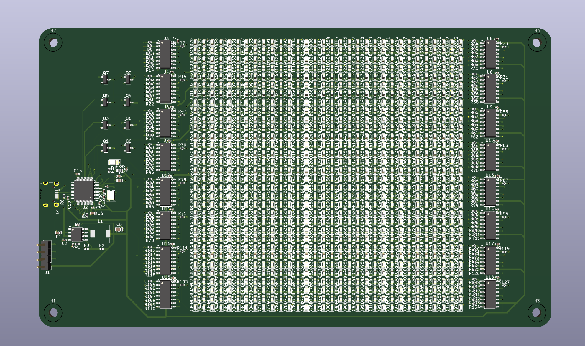
The PCB is organized into a few sections: the microcontroller, a buck converter, serial pins for testing, N-MOSFETs, shift registers, and N-MOSFETs. The shift registers and LEDs are within hierarchical sheets, so they are not visible from the high level-schematic.
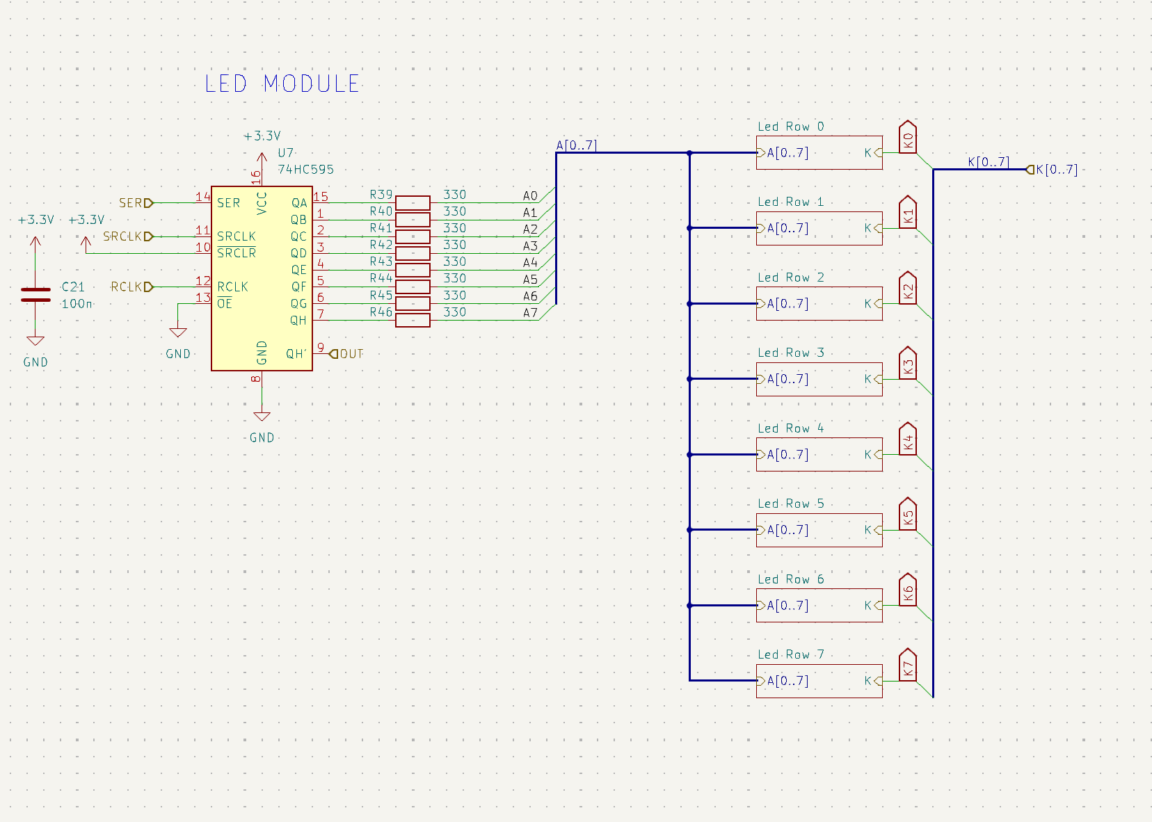
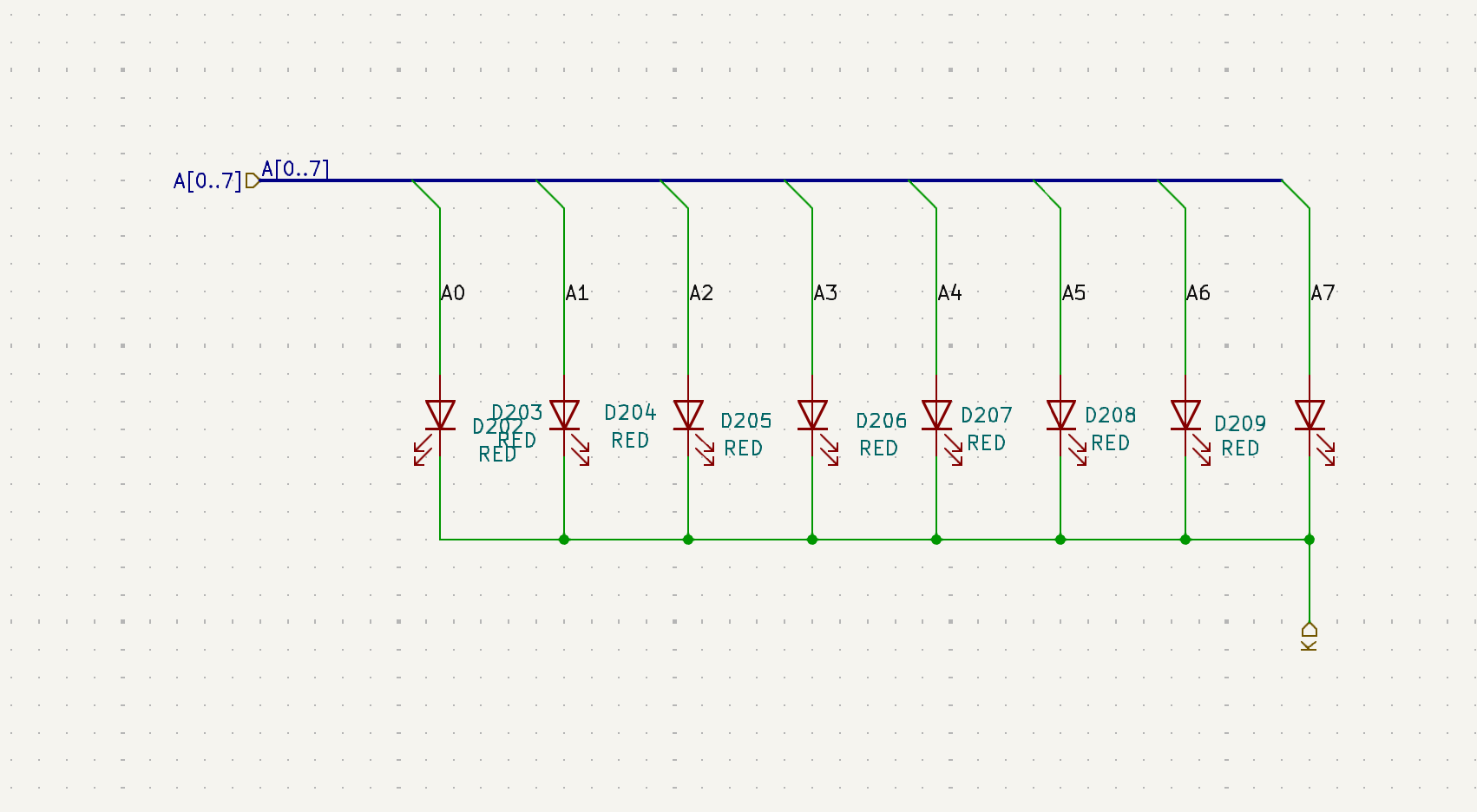
The structure can be seen in the photos below. Basically, there are 8 LEDs in an "LED row" that all are attached to the same pin off a single shift register. There are 8 such rows tied to each shift register. Each of these shift registers and 64 LEDs makes up an "LED Module." 4 LED Modules make up an "LED Group." These were mostly made for convenience when laying out the PCB. There are 4 shift registers in an LED module and 4 LED modules in an LED Group, for a total of 16 shift registers and 1032 LEDs.