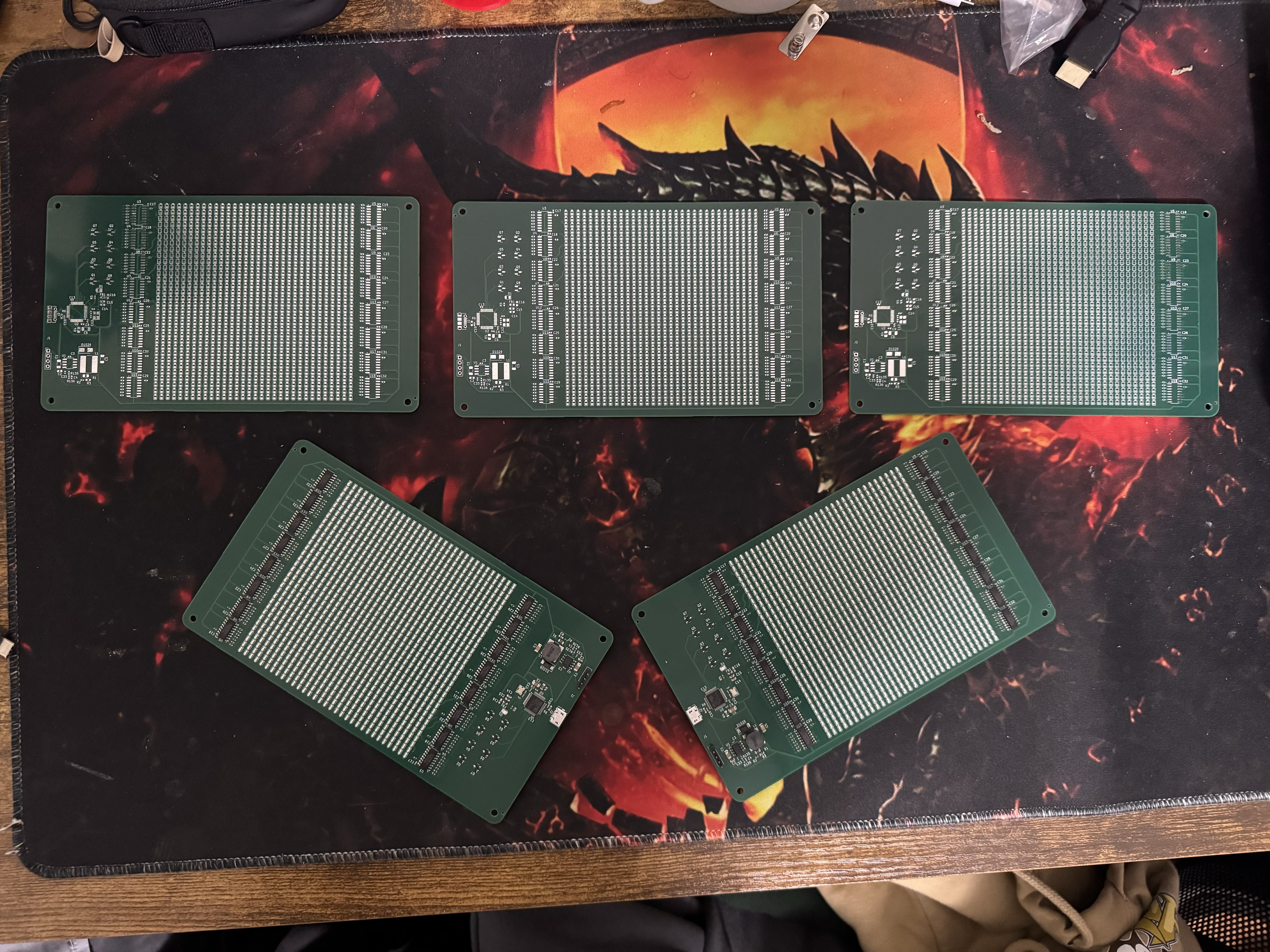
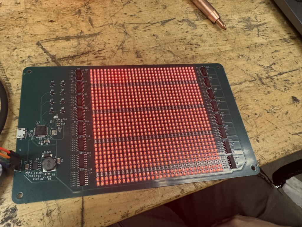
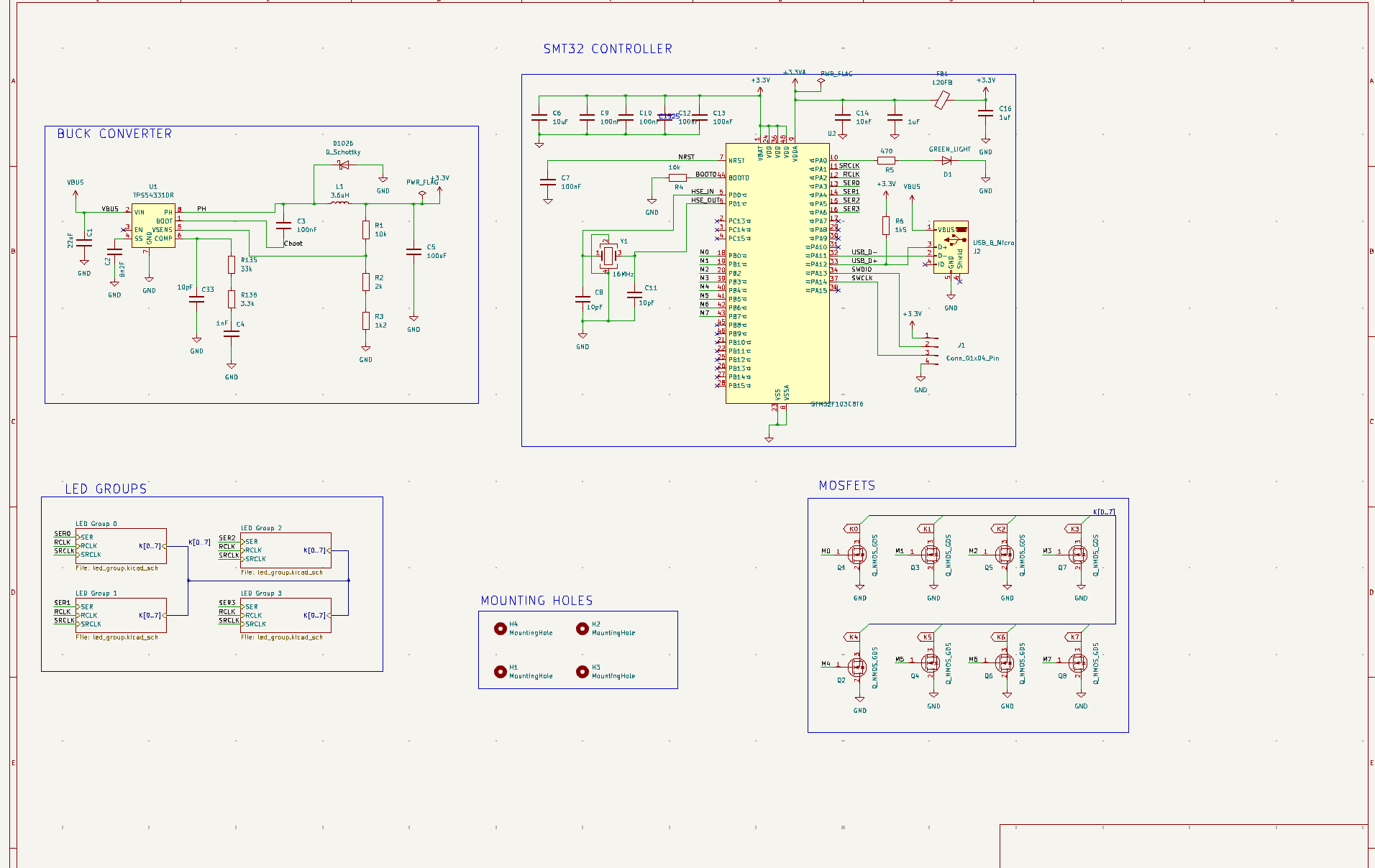
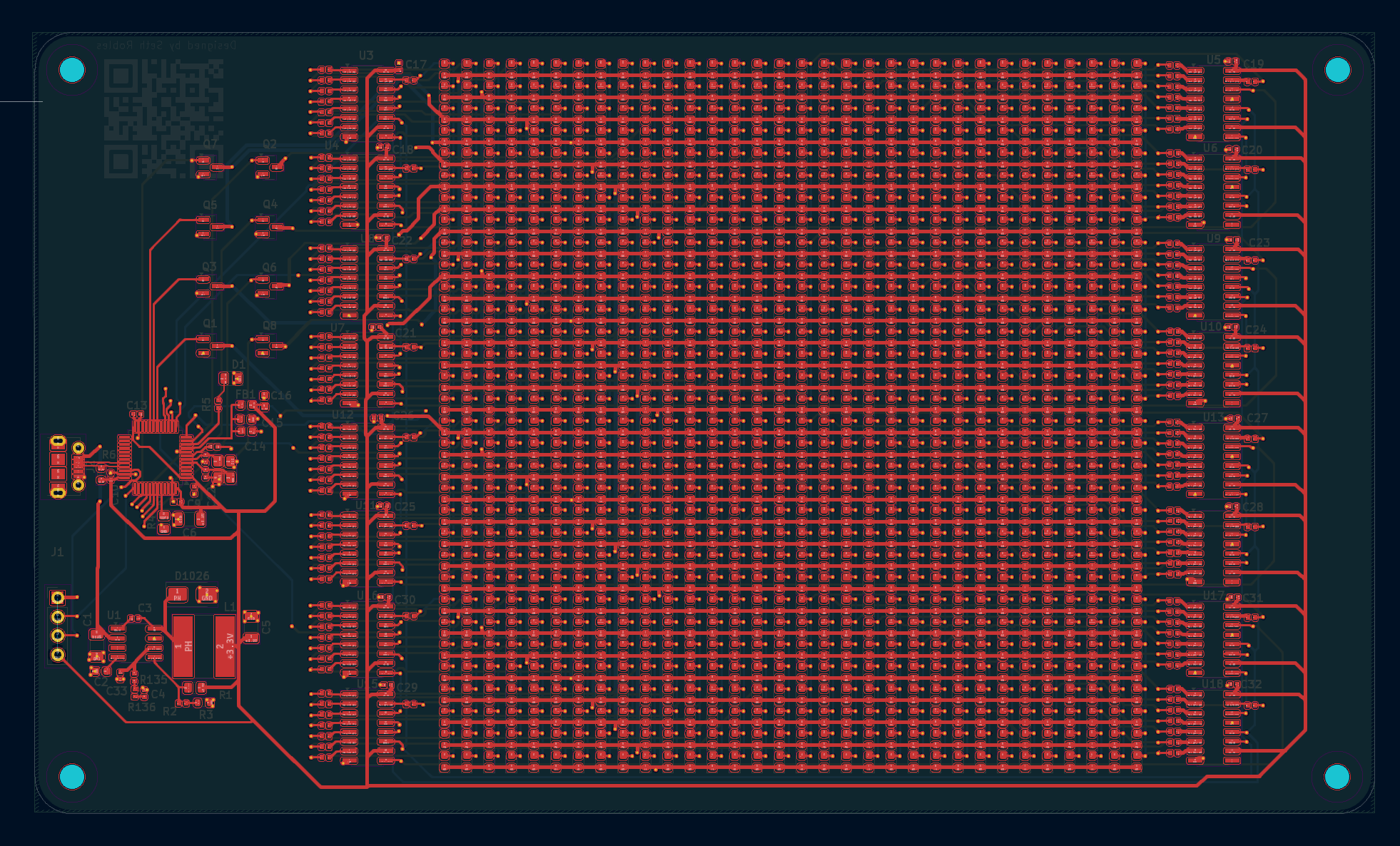
This is an red LED array (32x32) design in KiCAD and will eventually ordered from JLCPCB. It is a 4-layer PCB board is using a STM32 controller, 16 shift regiseters, and 8 N-fets. I have a corresponding blog post where I go more in depth about the design process. The project is under active development, and new features are being added frequently.
Thank you to my friend Miguel for providing a lot of guidance on this project.
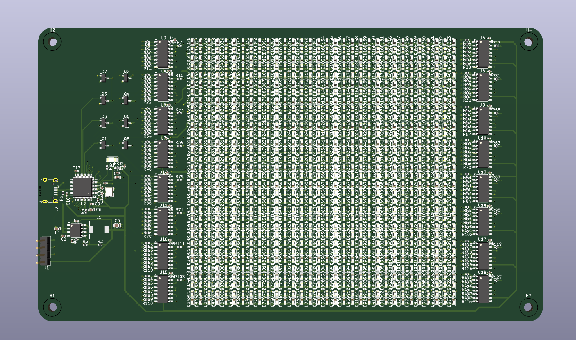
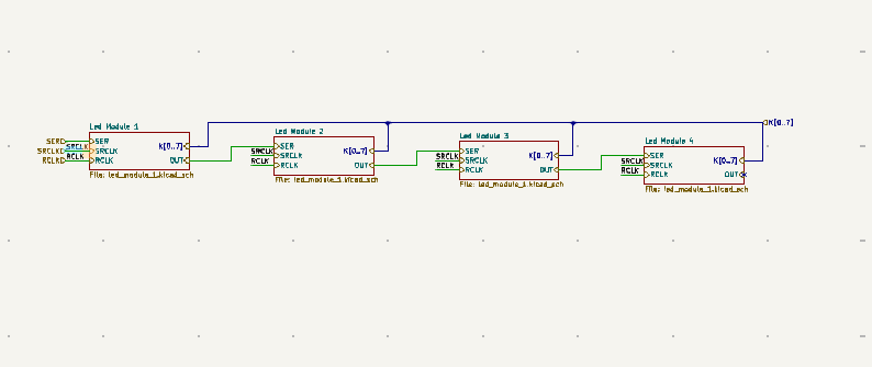
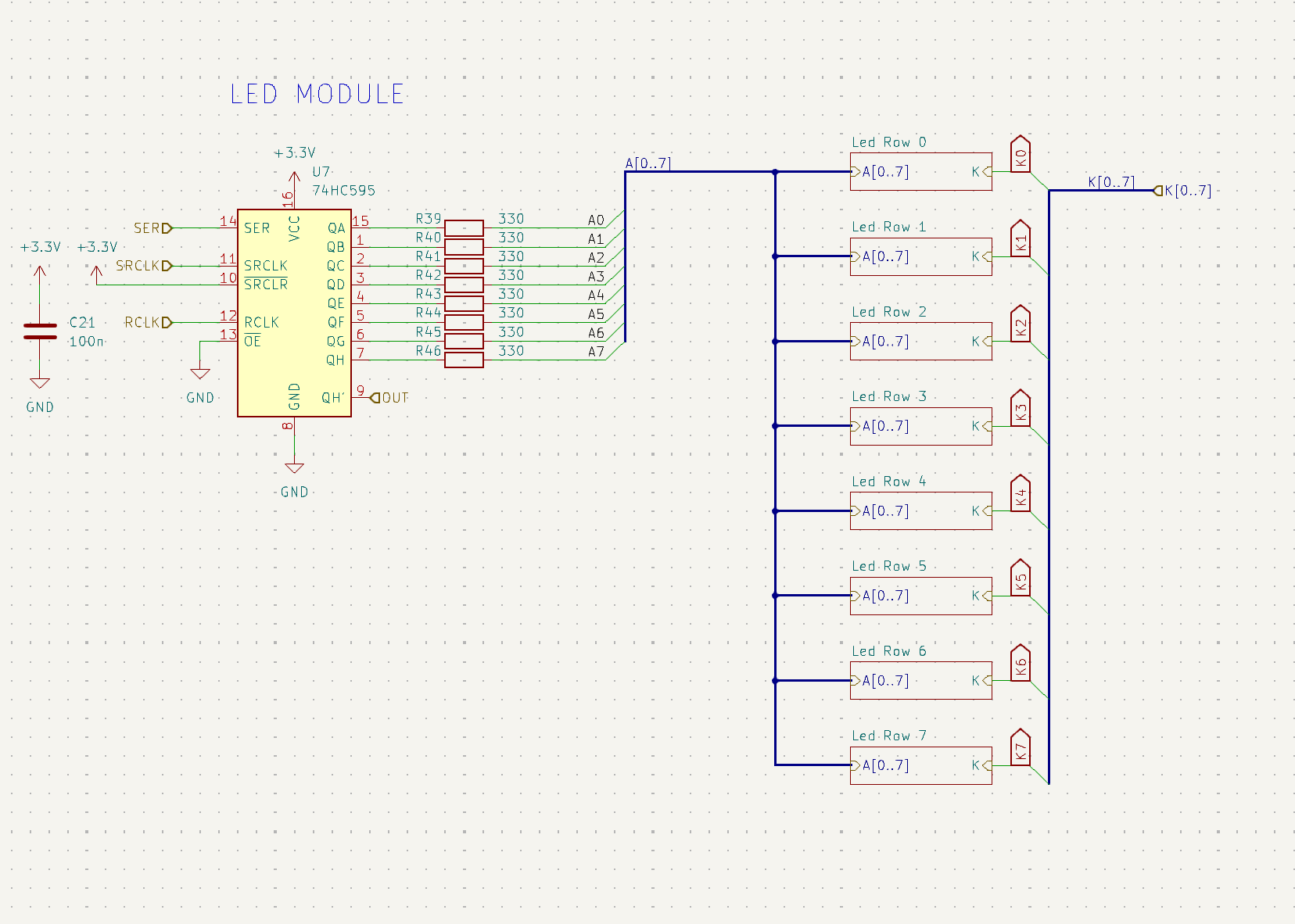
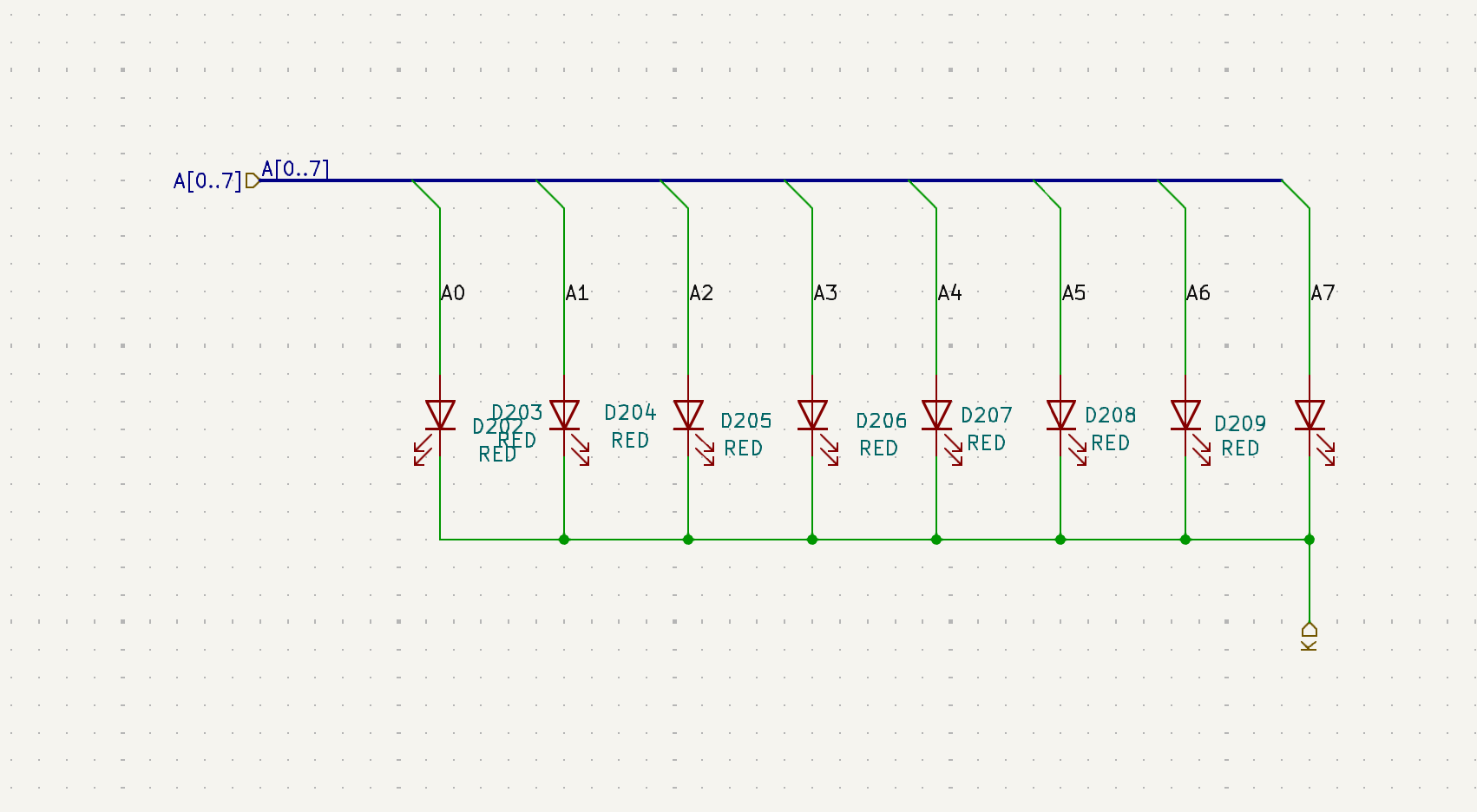
This project started as my first attempt at designing a PCB in KiCad — a 32×32 LED array driven by shift registers and MOSFETs, powered through a buck converter. I used hierarchical sheets to keep things organized, grouping the LEDs into modules and rows to make routing manageable.
A lot of time went into debugging small design choices: fixing LCSC part compatibility, redoing resistor ratios for the buck converter, and making sure the whole design passed ERC and DRC checks. I also learned how much manufacturing details can affect cost — my first JLCPCB quote came out to nearly $170 (half from customs and shipping), which I managed to cut down with coupons and advice from the MITERS Discord.
The final board includes sixteen shift registers controlling over a thousand LEDs, with each section modularized for testing and reuse. Even though it took a lot of iteration, it was a huge step up in understanding how electrical design, layout, and fabrication all come together.
Currently, I'm diving into STM32CubeIDE to write the firmware and flash the STM32 microcontroller. After some effort—and with help securing an ST-Link programmer—I was able to confirm the chip was working. I started with a simple blink code, powering the microcontroller directly off the ST-Link to verify that my first-ever PCB routing for the STM32 was sound.With the basic functionality confirmed, I moved on to analyzing the power stability. Using an oscilloscope, I measured the voltage ripple, which came out to a clean $20 \text{ mV}$. (I had some trouble with the image transfer from my thumb drive, but I'll upload the scope capture later!) My next steps will focus on producing code to get various messages / patterns to show on the LEDs.